Introduction To MASM Assembly
Assembly language is a low-level programming language used to create programs that directly control a computer's hardware, such as its CPU and memory. This language is composed ...
Jump to Section (34)
- Introduction
- Introduction To Registers
- General Purpose Registers
- Volatile vs Non-Volatile Registers
- RSP and RIP Registers
- RFLAGS Register
- MASM Program Structure
- Declaring Variables
- Declaring Strings
- Assembly Instructions
- mov Instruction
- add And sub Instructions
- call And ret Instructions
- lea Instruction
- and, or, xor, not Instructions
- jmp Instruction
- jz And jnz Instructions
- cmp Instruction
- push And pop Instructions
- leave Instruction
- Memory Access Specifiers
- Quadword Pointer - qword ptr
- Doubleword Pointer - dword ptr
- Byte Pointer - byte ptr
- Calling Functions
- Passing Parameters
- Returning Value
- Shadow Space
- Reserving RSP's Value
- Undoing Changes
- Caveat
- Reserving Shadow Space Example
- Video Demo
- Conclusion
- Companion Source Code
Introduction
Assembly language is a low-level programming language used to create programs that directly control a computer's hardware, such as its CPU and memory. This language is composed of "mnemonics," which are codes that can be interpreted by humans. Assembly language provides programmers with a way to write code that operates at a low level and offers a high degree of control over system operations. This language is commonly used for programming firmware, developing operating systems, and programming at the system level. By writing code in assembly language, programmers are able to work more closely with the underlying hardware and gain more precise control over the system's operations. There are several assembly language syntax types, however, the two most important ones are shown below.
- Intel Syntax This syntax is widely used in the Windows operating system and has a friendlier look.

- AT&T syntax This syntax is used by Unix systems and is the default syntax for the GDB debugger.

For this module, Intel Syntax will be used for both 64-bit and 32-bit architectures.
Note that this module is not intended to provide a comprehensive overview of the assembly language. Rather, it will focus on the basics of registers and instructions, with an emphasis on the 64-bit architecture, to provide a foundational understanding of how assembly language works. For a more comprehensive understanding of assembly, The Art of 64 Bit Assembly book is highly recommended.
Introduction To Registers
CPU registers are small, high-speed storage locations within the CPU that store data and addresses during the execution of instructions. Registers are used to temporarily hold data values that are being operated on, intermediate results of arithmetic or logical operations, and memory addresses for data access. Registers are an essential part of the CPU's architecture and provide fast access to data and instructions, enabling the CPU to perform calculations and execute instructions more quickly than if it had to access memory directly. Registers can be classified into four different categories:
- Special purpose application-accessible registers
- Segment registers
- Special purpose kernel-mode registers
- General purpose registers
This module will focus solely on General-purpose registers, as they are the registers that are commonly used by programmers. The other types of registers are used primarily for kernel-mode development and debugging purposes, which are beyond the scope of this module.
General Purpose Registers
In 32-bit CPUs, the general purpose registers look like the following, based on Microsoft's documentation on the x86 architecture
| 32-bits | 16-bits | 8-bits |
|---|---|---|
| EAX | AX | AH / AL |
| EBX | BX | BH / BL |
| ECX | CX | CH / CL |
| EDX | DX | DH / DL |
| ESI | SI | SIL |
| EDI | DI | DIL |
| EBP | BP | BPL |
| ESP | SP | SPL |
| R8D | R8W | R8L |
| R9D | R9W | R9L |
| R10D | R10W | R10L |
| R11D | R11W | R11L |
| R12D | R12W | R12L |
| R13D | R13W | R13L |
| R14D | R14W | R14L |
| R15D | R15W | R15L |
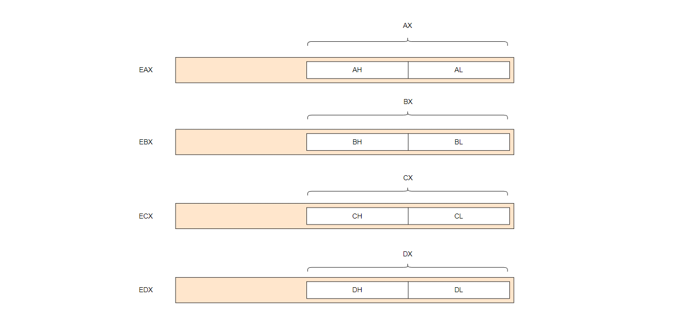
The first 4 registers EAX, EBX, ECX, EDX are shown below.
On the other hand, in 64-bit CPUs, the general purpose registers are as below, based on Microsoft's documentation on the x64 architecture
| 64-bits | 32-bits | 16-bits | 8-bits |
|---|---|---|---|
| RAX | EAX | AX | AH / AL |
| RBX | EBX | BX | BH / BL |
| RCX | ECX | CX | CH / CL |
| RDX | EDX | DX | DH / DL |
| RSI | ESI | SI | SIL |
| RDI | EDI | DI | DIL |
| RBP | EBP | BP | BPL |
| RSP | ESP | SP | SPL |
| R8 | R8D | R8W | R8B |
| R9 | R9D | R9W | R9B |
| R10 | R10D | R10W | R10B |
| R11 | R11D | R11W | R11B |
| R12 | R12D | R12W | R12B |
| R13 | R13D | R13W | R13B |
| R14 | R14D | R14W | R14B |
| R15 | R15D | R15W | R15B |
Again, the first 4 registers RAX, RBX, RCX, RDX are shown below.
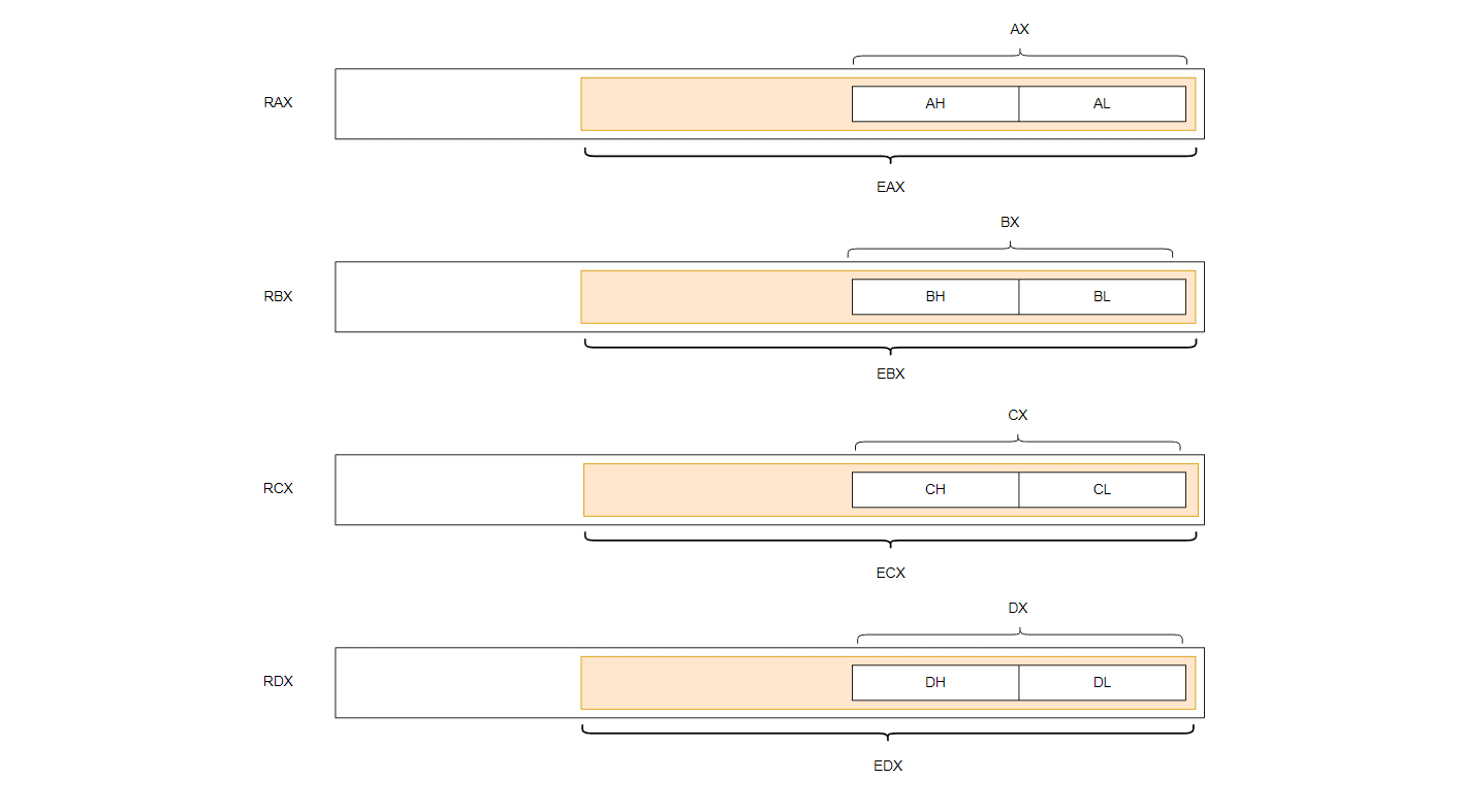
It is important to note that the registers for both 32-bit and 64-bit systems are not independent, as shown in the images. Instead, they are arranged in a hierarchical structure, where registers of larger size overlay registers of a smaller size. In the case of a 64-bit system, for example, the 64-bit registers are placed over the 32-bit registers, which in turn are placed over the 16-bit registers, and so on. This hierarchical arrangement ensures that backward compatibility is maintained for programs written for older architectures while providing access to the full range of features offered by the newer architectures.
Therefore, modifying one register will affect the value of the registers that overlay it. For example, changing the value of RBX will cause the value of EBX to be modified, which in turn affects the value of BX. This, in turn, will affect the values of the BH and BL registers. This hierarchical relationship between the registers means that changing the value of a higher-level register will affect the values of all lower-level registers that overlay it. This hierarchical relationship also implies that modifying a lower-level register will similarly affect the values of all higher-level registers that encompass it. For example, modifying the value of BL will impact the value of BX, which will then influence the value of EBX, and subsequently modify the value of RBX.
The purpose of sub-registers is to optimize time and computational resources. For example, it is more efficient to store an unsigned integer, which occupies 4 bytes, in either AH or AL instead of occupying the entire 64 bits of the RAX register for storing the same value.
Volatile vs Non-Volatile Registers
During a function or procedure call in assembly language (assembly functions are called procedures), certain registers automatically alter in value, and these registers are known as non-volatile registers. To alter the values of these registers, a function or procedure must preserve their original values across the call, modify them as necessary, and restore the original values prior to returning from the called function or procedure. The following registers are typically classified as non-volatile registers:
- x64 Systems -
RSP,RSI,RDI,RBP,RBX,R12-15. - x86 Systems -
EBX,EBP,ESI,EDI,R12-R15D.
On the other hand, volatile registers do not need to be saved across a function/procedure call:
- x64 Systems -
RCX,RAX,RDX,R8-11. - x86 Systems -
ECX,EAX,EDX,R8-11D.
RSP and RIP Registers
The RIP register on 64-bit systems or EIP on 32-bit systems, is a special-purpose register that holds the memory address of the next instruction to be executed. The processor automatically increments the RIP/EIP register after executing each instruction, so that it points to the next instruction in memory.
On the other hand, the RSP register on 64-bit systems or ESP on 32-bit systems is called the stack pointer register. This register holds the memory address of the top of the stack. The stack is a memory region that's used to store temporary data and function call information, and the RSP/ESP register is used to keep track of the current location on the stack.
RFLAGS Register
The RFLAGS Register Flags) register is a special-purpose register that contains several status and control flags that are used by the processor to control program execution and detect certain conditions during program execution (e.g. if-statements).
On 64-bit machines, the RFLAGS register is 64 bits in size, while on 32-bit machines, it is 32 bits. The register comprises several single-bit Boolean values, where each bit corresponds to a specific flag. A flag is set to 1 when it is activated, and 0 when it is not. It is essential to note that the majority of RFLAGS flags are reserved for kernel- mode functions, and are of limited concern to general users. The following image illustrates the appearance of the first 16 bits of the RFLAGS register:
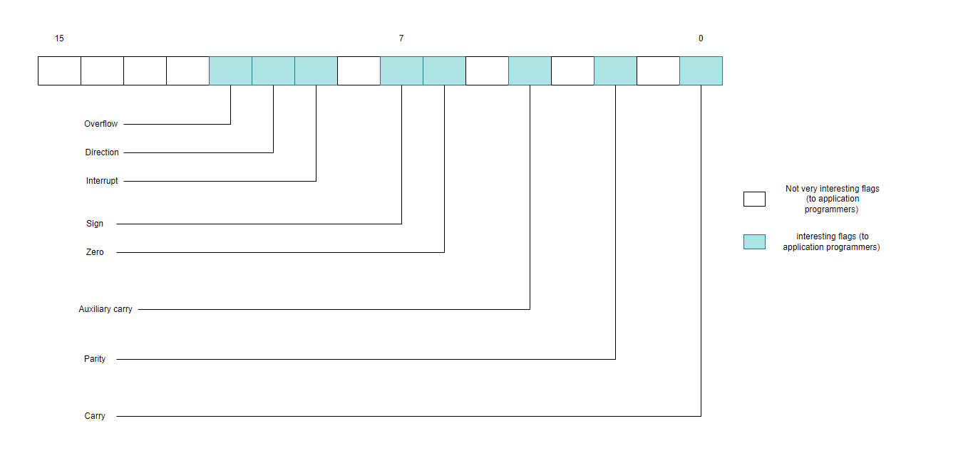
The relevant flags are explained below:
Carry Flag (CF) - Bit (0)This flag is set when an arithmetic operation generates a carry or borrow. It is also used in bitwise operations, where it indicates whether the result of the operation has a carry-out from the most significant bit.Parity Flag (PF) - Bit (2)This flag is set when the least significant byte of the result of an arithmetic operation has an even number of set bits.Zero Flag (ZF) - Bit (6)This flag is set when the result of an arithmetic operation is zero.Sign Flag (SF) - Bit (7)This flag is set when the result of an arithmetic operation is negative.Overflow Flag (OF) - Bit (11)This flag is set when an arithmetic operation generates a signed overflow, meaning that the result is too large to be represented in the available number of bits.
It is worth mentioning that the carry, overflow, sign, and zero flags are called conditional codes. The state of these flags determines the result of previous computations (e.g. string comparing).
MASM Program Structure
MASM or Microsoft Macro Assembler is an assembler that uses the Intel syntax to assemble assembly code in a Visual Studio project, as it is a part of the Visual Studio suite. A typical stand-alone MASM program is shown below, where a semicolon denotes a comment.
; Data section: contains variable and memory values, adding this section is optional
; Variables can be declared below the ".data" directive
.data; Code section: contains the assembly code/functions
; Assembly functions can be declared below the ".code" directive
.code; MASM function declaration
main PROC ; Start of function "main"
; Assembly code of "main"
ret ; Return from "main"
main ENDP ; End of function "main" ; The "end" directive marks the end of the source file
endDeclaring Variables
To declare variables in MASM assembly, one must specify them within the data section of the file, which is created using the .data directive, as previously shown. The following form is typically employed to declare a variable:
VarName directive VarValueWhere VarName is the variable name to be declared and directive is one of MASM's data declaration directives listed below:
wordUnsigned 16-bit value (word).swordSigned 16-bit integer value.dwordUnsigned 32-bit value (double word).sdwordSigned 32-bit integer value.qwordUnsigned 64-bit value (quad word).sqwordSigned 64-bit integer value.oword128-bit value (octal word).tbyteUnsigned 80-bit value.real432-bit floating point value.real864-bit floating point value.real1080-bit floating point value.byteUnsigned 8-bit value.sbyteSigned 8-bit integer value.
Finally, VarValue represents the variable's value. The following are some examples of declaring variables in MASM assembly.
WordVariable      word         2
sWordVariable     sword       -2
FloatVariable     real8       3.1
It's possible to initialize a variable with a hexadecimal value using the h suffix.
DwordVariable dword 10h ; this is 10 in hex, which is 16 in decimalDeclaring Strings
One can declare a string using the byte MASM directive, which is done as shown below
StringVar byte 'This is a string', 0 ; we add "0" to null-terminate the string The MASM assembler interprets the above string as an array of hexadecimal characters. In the following example, one can incorporate the new line character (represented by \n in C . It is important to note that the hexadecimal value of \n is 10, or 16 in decimal format, as illustrated in the following code snippet:
StringVar byte 'This is a string with a new line', 10, 0 ; "10" represents the new line character and is equal to 16 in decimal formatSince the byte directive in MASM assumes that it is dealing with hexadecimal characters, it is unnecessary to include the h suffix to represent the value of 10 in the above example.
Assembly Instructions
This section will discuss some of assembly's most common instructions. For more instructions visit felixcloutier.com or Intel's 64 and IA 32 Architectures Software Developer Manuals.
mov Instruction
The mov instruction is the most frequently used instruction in assembly. As the name suggests, the mov instruction is used to transfer data between registers or memory locations. The basic syntax for the mov instruction, in MASM assembly, is as follows:
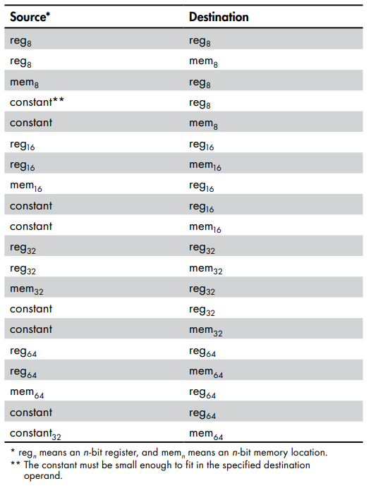
mov destination, sourceBoth, destination and source operands can be a general-purpose register or a memory variable. In addition to that, the source operand can be also a constant. The mov instruction has certain limitations to its usage, including:
- Only one of the source and destination operands can be a memory variable.
- Both the source and destination operands must be of the same size. Mixing different operand sizes within a single
movinstruction will result in a compilation error.
The following table is from The Art of 64 Bit Assembly Language book, showing all the legal mov instruction operands.
Examples of using the mov instruction are the following
mov rax, 1234     ; move the value 1234 into the RAX register
mov rax, rbx      ; move the value in the RBX register into the RAX register
In assembly language, square brackets [] are utilized to indicate indirect memory access, which is also referred to as a memory operand. Instead of accessing the operand itself, this method accesses the content of the memory location pointed to by the operand enclosed in the square brackets. In the example below, the first instruction moves the value of 0x05 into the al register. The second instruction employs square brackets to access the memory location pointed to by the ebx register, then moves the value stored in the al register to that memory location.
mov al, 5h        ; move the value 0x05 into the AL register
mov [ebx], al     ; move the value in AL to the memory location pointed to by the EBX register
add And sub Instructions
The add and sub instructions, add and subtract two operands, respectively. They share the same syntax that's shown below.
add destination, source
sub destination, source
Both operands can be either a register or a memory location. Furthermore, a constant can be used as the source operand. Upon execution, the resulting values of both instructions are stored in the destination operand. A sample representation of this can be seen below.
add destination, source                   ; destination = destination + source
sub destination, source                   ; destination = destination - source
Examples of using the add instruction are shown below.
add rax, rbx                     ; add the value in RBX to the value in RAX and store the result in RAX
add rax, [rcx]                   ; add the value in the memory location at RCX to the value in RAX and store the result in RAX
add [rax], 10                    ; add the value 10 to the memory location at RAX and store the result in that memory location
Examples of using the sub instruction are shown below.
mov al, 12h       ; move the value 0x12 into the AL register
mov bl, 5h        ; move the value 0x05 into the BL register
sub al, bl        ; subtract the value in BL from the value in AL and store the result in AL. AL's value is now '13'
call And ret Instructions
In MASM, a procedure can be called using the call instruction. The ret instruction is then used to return execution back to the caller, which serves a similar purpose as the return statement in C/C. The call instruction's syntax is shown below, where ProcedureName is the procedure name that is called.
call ProcedureNameThe ret instruction does not require any operands or parameters, and it does not return a value. Its purpose is to indicate that the current function has finished executing and to return control to the caller function. The address to which the ret instruction returns is determined by the value at the top of the stack.
retThe following is an example of using the call and ret instructions.
.code

DummpProc     PROC
      mov rcx, 3        ; dummy code
      add rbx, 2
      sub esi, 1
      ret               ; return execution back to "main"
DummpProc ENDPmain PROC
call DummpProc ; calling "DummpProc"
ret ; function "main" is terminated
main ENDP
endlea Instruction
The lea or Load Effective Address instruction is used to calculate the effective memory address of a location and load it into a register, without actually accessing the memory location itself. The lea instruction can be thought of as the equivalent of the C/C "address-of" operator &. The general format of the lea instruction is:
lea reg64, source Where reg64 (the destination operand) represents any 64-bit general-purpose register that will hold the address of the source memory location. The source operand can be a memory address, a register that holds a memory address, or a variable. An example of using the lea instruction is shown below.
StringVar byte 'String Variable', 0       ; A dummy string variable
lea rcx, StringVar                        ; Load the address of the StringVar variable into RCX. RCX is now equal to &StringVar[0]
and, or, xor, not Instructions
The logical operators and, or, xor, and not are all used to perform logical operations on bit patterns. These instructions are discussed in further detail below:
and
The and instruction performs a bitwise and operation between two operands and stores the result in the destination operand. The syntax of the and instruction is as follows:
and destination, sourceor
The or instruction performs a bitwise or operation between two operands and stores the result in the destination operand. The syntax of the or instruction is as follows:
or destination, sourcexor
The xor instruction performs an exclusive OR operation between two operands and stores the result in the destination operand. One common use of the xor instruction is to clear a register, which is achieved by XORing the register with itself. The syntax of the xor instruction is as follows:
xor destination, sourcenot
The not instruction performs a bitwise not operation on the operand and stores the result in the destination operand. The syntax of the not instruction is as follows:
not destinationExamples
The following are some examples of the previously mentioned instructions.
mov ax, 11FFh
and ax, 010Fh     ; The AX register is now equal to 0x010F

mov bx, 0011h
or  bx, 1010h     ; The BX register is now equal to 0x1011

mov cx, 1101h
xor cx, 1111h     ; The CX register is now equal to 0x0010

mov eax, FFh
xor eax, eax      ; The EAX register is now equal to 0x00 - This is faster than 'mov eax, 0'

mov ax, 1100h
not ax            ; The AX register is not equal to 0xEEFF
jmp Instruction
The jmp instruction, also known as a jump instruction, is used for unconditional branching or jumping. When the jmp instruction is executed, the execution is directly transferred to the destination operand without performing any checks. The jmp instruction looks as follows:
jmp destination ; Where 'destination' is where to jump The destination operand can be a register, memory location, or a label. In assembly language, a label is a name given to a specific location in the program's code, which is usually defined using a colon (:) at the end of a name or identifier. Here is an example that demonstrates the usage of labels and the jmp instruction.
.code

main PROC
      add eax, 2              ; dummy code
      xor ax, 5
      mov bx, ax
      jmp LabelName           ; Jump to execute 'LabelName'
      mov eax, 100            ; These instructions won't get executed
      mov ebx, 100
LabelName:
      xor eax, eax            ; LabelName's code
      sub ebx, 2
      ret
main ENDP

end
jz And jnz Instructions
The jz and jnz instructions are examples of conditional jump instructions, which allow for conditional execution of code. These instructions work by checking a specified flag (stored in the RFLAGS register) to see if a particular condition is true (flag is 1 or false (flag is 0 . If the test succeeds, the program branches to a target label; otherwise, it continues execution with the instruction following the conditional jump instruction.
jz, which stands for "jump if zero", jumps if the zero flag is set 1 , while jnz ("jump if not zero") executes the jump if the zero flag is clear 0 . There are many other conditional jump instructions, but the following are some of the most frequently encountered instructions:
jcJump if Carry Executes the branch if the Carry Flag is set 1 .jncJump if Not Carry Executes the branch if the Carry Flag is not set 0 .joJump if Overflow Executes the branch if the Overflow Flag is set 1 .jnoJump if Not Overflow Executes the branch if the Overflow Flag is not set 0 .jsJump if Sign Executes the branch if the Sign Flag is set 1 .jnsJump if Not Sign Executes the branch if the Sign Flag is not set 0 .jeJump if Equal Executes the branch if the Zero Flag is set 1 .jneJump if Not Equal Executes the branch if the Zero Flag is not set 0 .jaJump if Above Executes the branch if the left operand is greater than the right operand.jaeJump if Above or Equal Executes the branch if the left operand is greater than or equal to the right operand.jbJump if Below Executes the branch if the left operand is less than the right operand.jbeJump if Below or Equal Executes the branch if the left operand is less than or equal to the right operand.
cmp Instruction
The cmp or compare instruction is the most useful instruction to execute prior to a conditional jump instruction. It has the following syntax:
cmp First, SecondThe cmp instruction subtracts the second operand from the first operand and sets the condition code flags based on the result of the subtraction. However, it is important to note that the cmp instruction does not store the difference back into the first (destination) operand, even though it subtracts both operands. The following examples demonstrate how cmp can set a flag's value based on the value of its operands.
- If the first operand is greater than the second operand, the Carry flag is cleared and the Sign flag is set if the result is negative.
- If the second operand is greater than the first operand, the Carry flag is set and the Sign flag is cleared.
- If the two operands are equal, the Zero flag is set and the Carry and Sign flags are cleared.
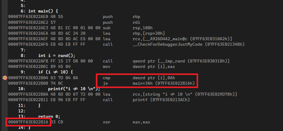
As mentioned earlier, the cmp is often followed with a conditional jump instruction. To show this, the following example shows the disassembly of a simple if-statement, and the relation between cmp and a je (jump if equal) instruction.
1.The following is a simple C code that includes an if-statement to be compiled using Visual Studio.
#include <stdio.h>

int main() {

    int i = rand();
    // if "i" is not equal to 10
    if (i != 10) {
        printf("i != 10 \n");
    }

    return 0;
}
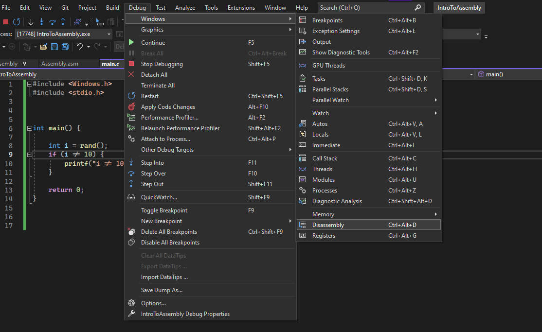
2.After compiling, one should view the "Disassembly" tab, after placing a breaking point while running in debug mode.
3.The following assembly code shows a je instruction being found directly below a cmp instruction. If je is executed (i is equal to 10 , the printf call is not executed, on the other hand, if i is not equal to 10, the je instruction fails, executing the printf call.
push And pop Instructions
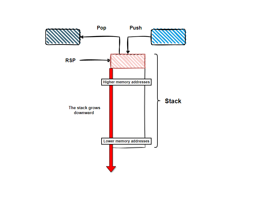
The push and pop instructions are commonly used to manipulate the stack, which is a region of memory used for temporary data storage during program execution. The push instruction takes a value from a register or memory location and pushes it onto the top of the stack. This adds the value to the stack, causing the stack pointer (RSP register) to decrement to indicate the new top of the stack. The push instruction's syntax is shown below:
push SourceWhere Source is a register or a memory location containing the value to be pushed onto the stack. For example, push eax would push the value of the eax register onto the stack.
On the other hand, the pop instruction takes the value at the top of the stack and pops it off the stack, storing it in a register or memory location. As a result, the stack pointer (RSP register) is incremented to point to the next value on the stack. The syntax for the pop instruction syntax is shown below:
pop DestinationWhere destination is the register or memory location where the value from the stack will be stored. For example, pop ebx would pop the value at the top of the stack into the ebx register.
The following image shows the relation between the RSP register with the push and pop instructions.
To further understand how push and pop operate, an example is presented below.
SimpleAsmFunc PROC

    push 3          ; rsp - 8
    push 2          ; rsp - 8
    push 1          ; rsp - 8

    mov eax, [rsp]       ; eax = 1
    mov ebx, [rsp + 8]       ; ebx = 2
    mov ecx, [rsp + 16]      ; ecx = 3

    add rsp, 24          ; pop x3

    ret

SimpleAsmFunc ENDP
When all the push instructions are done, the stack looks like this:
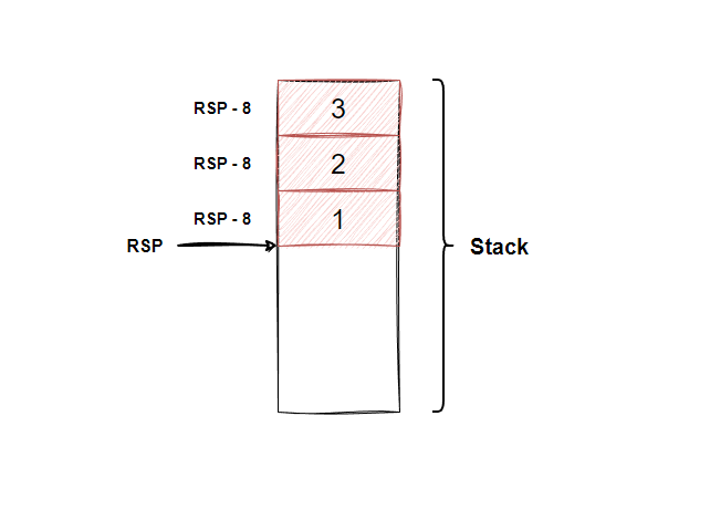
The mov instructions add the offset of the pushed value from the stack pointer to set the registers to the value located at the specified offset of the stack. This process can be visualized in the image below.
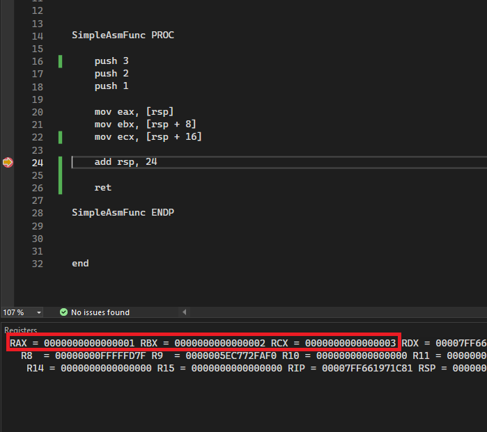
The add rsp, 24 instruction is used to adjust the value of the stack pointer (RSP) to its original value before the previous push instructions. This is equivalent to simulating three pop instructions since each pop instruction removes 8 bytes from the stack, and there were three push instructions before the add rsp, 24 instruction.
leave Instruction
The leave instruction is used to clean up and exit a subroutine or function. When executed, it first moves the value of the base pointer register (RBP) to the stack pointer register (RSP). It then pops the value of the base pointer register from the stack, restoring it to its previous value. This instruction is often used to free reserved shadow spaces (which will be discussed later). Essentially, the leave instruction performs the same task as the following instructions:
mov rsp, rbp
pop rbp
Memory Access Specifiers
In MASM assembly language, memory access specifiers are used to indicate the size and the type of data being accessed in memory, these specifiers act like type- casting in a programming language. The most commonly used memory access specifiers are explained below.
Quadword Pointer - qword ptr
A quadword pointer is used to access a 64-bit data value stored in memory. It is specified using the qword ptr specifier. For instance, if you want to access a 64-bit integer value stored in a particular memory location, you can use the qword ptr specifier with the mov instruction. Here are two examples:
mov rax, qword ptr [rbx]         ; Example 1
mov rax, qword ptr [rsp + 32h]   ; Example 2
In the first example, the 64-bit integer value stored at the memory location pointed to by the rbx register is accessed using the qword ptr specifier with the mov instruction. In the second example, the qword ptr specifier is used with the mov instruction to access the 64-bit integer value stored at an offset of 32h bytes from the rsp register.
Doubleword Pointer - dword ptr
A doubleword pointer is a memory addressing mode that specifies the size of 32-bit data in memory. It is used when manipulating data stored in memory, particularly 32- bit integer values. To access a 32-bit integer value stored at a specific memory location, the dword ptr specifier should be used in the instruction, as shown in the following examples:
mov dword ptr [ebx], 12345678    ; Example 1: stores a 32-bit integer value in memory
mov eax, dword ptr [edx + 4] ; Example 2: loads a 32-bit integer value from memory into the eax register
Byte Pointer - byte ptr
A byte pointer is used to indicate the size of 8-bit data in memory. To access a single byte of data stored at a specific memory location, the byte ptr specifier is used.
mov al, byte ptr [edx + 2]   ; Example 1
mov byte ptr [ebx + 8], 55h ; Example 2
Calling Functions
Calling functions in assembly can happen in one of the following scenarios:
1.The first scenario involves calling an assembly function from another assembly function. This is done using the call instruction to jump to the callee, with the ret instruction used to return to the caller.
2.The second scenario involves calling an assembly function from C. To import an assembly function to a C file, the function prototype should be defined in the C file with the extern keyword. This informs the compiler that the function is already defined in another file, such as an .asm file. An example of calling an assembly function from C is shown below.
/*
      main.c file
*/

#include <stdio.h>

extern void SimpleAsmFunc(); // SimpleAsmFunc's prototype. Parameters and function return data type is covered in a later section

int main (){
      printf("[i] Calling 'SimpleAsmFunc' ... ");
      SimpleAsmFunc();
      printf("[+] Done");
      return 0;
}; The asm file that includes the definition of 'SimpleAsmFunc'
.code
SimpleAsmFunc PROC
xor rcx, rcx ; SimpleAsmFunc's code
add rcx, 2
ret
SimpleAsmFunc ENDP
end3.Calling a C function from within an assembly file. To do this, the assembly code must first declare the C function using the externdef directive. This tells the MASM assembler that the symbol (i.e. function) is defined in another module. The externdef directive has the following syntax:
externdef symbol_name:typeHere, symbol_name is the name of the function to be defined, and type specifies the type of the function. For example, if there is a C function named foo defined in a C file, we can declare it in the assembly file using the externdef directive as follows:
externdef foo:proc ; This will tell MASM that "foo" is a procedureThe following is an example of calling a C function, SimpleCFunc from assembly.
/*
      main.c file
*/

#include <stdio.h>

// Dummy C function
void SimpleCFunc() {

    int i = 100;
    i = i * (i + 7) >> 3;
    i += i/2;

    if (i > 100)
       i -= 20;
        else
       i += 20;
}int main() {
// You can port "AsmFunc" here and call it
return 0;
}; The asm file that calls 'SimpleCFunc'
externdef SimpleCFunc:proc ; Using externdef to declare "SimpleCFunc" as a procedure defined in an other file
.code
AsmFunc PROC
call SimpleCFunc ; Calling SimpleCFunc
ret
AsmFunc ENDP
endNote that even if the C function did require parameters, the externdef directive will remain the same since parameters are passed via registers, as explained in the following section.
Passing Parameters
Once you've learned how to create and call an assembly procedure, the next step is to pass parameters to it. In 64-bit assembly, parameters can be passed in two ways:
- The first four parameters (if they exist) are passed through the registers
RCX,RDX,R8, andR9. The first parameter is passed throughRCX, the second throughRDX, and so on. These parameters are known as register parameters. - If a procedure requires more than four parameters, they are pushed onto the stack. These parameters are known as stack parameters, and the stack must be 16-byte aligned to accommodate them.
The first stack parameter 5th procedure parameter) is located at a specific offset from the rsp register, depending on the function's calling convention, which won't be discussed in this module due to the complexity of the topic.
In a 64-bit MASM function, the fifth parameter is usually located at an offset of [rsp + 40], which is 40 bytes beyond the current stack pointer. Even though the first four parameters are passed in registers according to the Microsoft calling convention, 32 bytes of stack space are reserved for them 8 bytes per parameter) to make sure that there is enough room on the stack to store these parameters if needed. Additionally, 8 bytes are also reserved for the function return address, which the rsp register points to at the time of the function call. By adding these values together 32 and 8 , the offset for the first stack parameter is determined to be [rsp + 40].
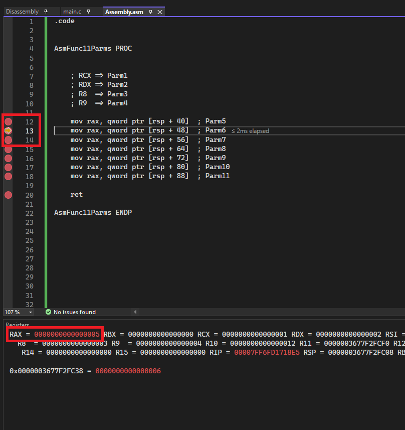
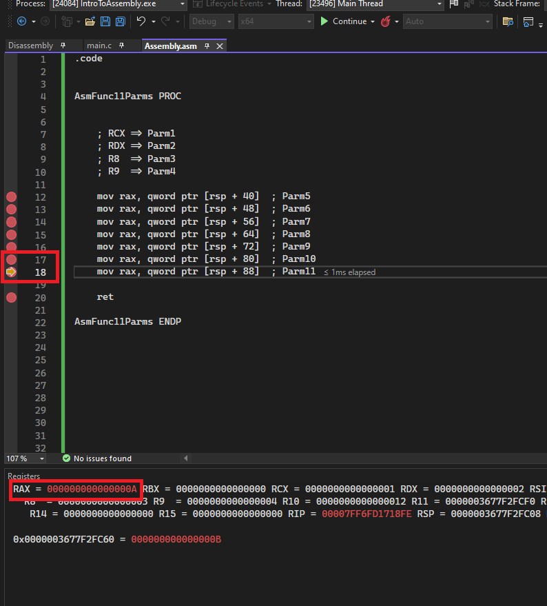
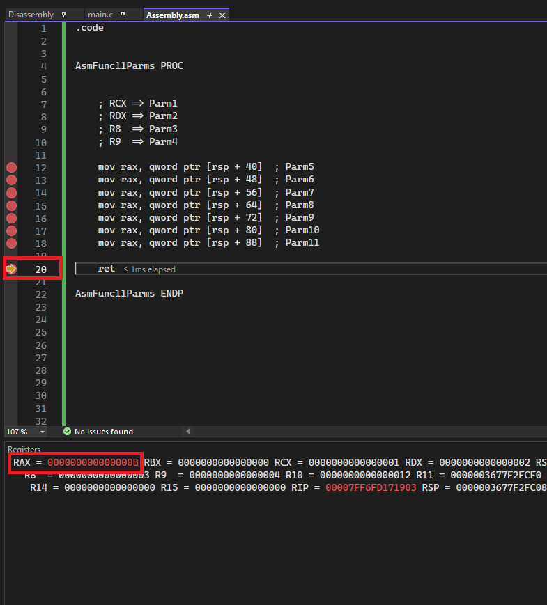
The AsmFunc11Parms procedure is called from a C file, passing 11 parameters. Although AsmFunc11Parms doesn't perform any operation, during debugging it's possible to observe the passed parameters being moved to the rax register. This can be seen in the following example.
AsmFunc11Parms PROC

    ; RCX => Parm1
    ; RDX => Parm2
    ; R8  => Parm3
    ; R9  => Parm4

    mov rax, qword ptr [rsp + 40]  ; Parm5
    mov rax, qword ptr [rsp + 48]  ; Parm6
    mov rax, qword ptr [rsp + 56]  ; Parm7
    mov rax, qword ptr [rsp + 64]  ; Parm8
    mov rax, qword ptr [rsp + 72]  ; Parm9
    mov rax, qword ptr [rsp + 80]  ; Parm10
    mov rax, qword ptr [rsp + 88]  ; Parm11

    ret

AsmFunc11Parms ENDP
Calling AsmFunc11Parms from C is done below
#include <Windows.h>

extern int AsmFunc11Parms(PVOID Parm1, PVOID Parm2, PVOID Parm3, PVOID Parm4, PVOID Parm5, PVOID Parm6, PVOID Parm7, PVOID Parm8, PVOID Parm9, PVOI
D Parm10, PVOID Parm11);

int main() {
    AsmFunc11Parms(1, 2, 3, 4, 5, 6, 7, 8, 9, 10, 11);
    return 0;
}
The below image shows the values of the first four parameters inside the RCX, RDX, R8 and R9 registers respectively.
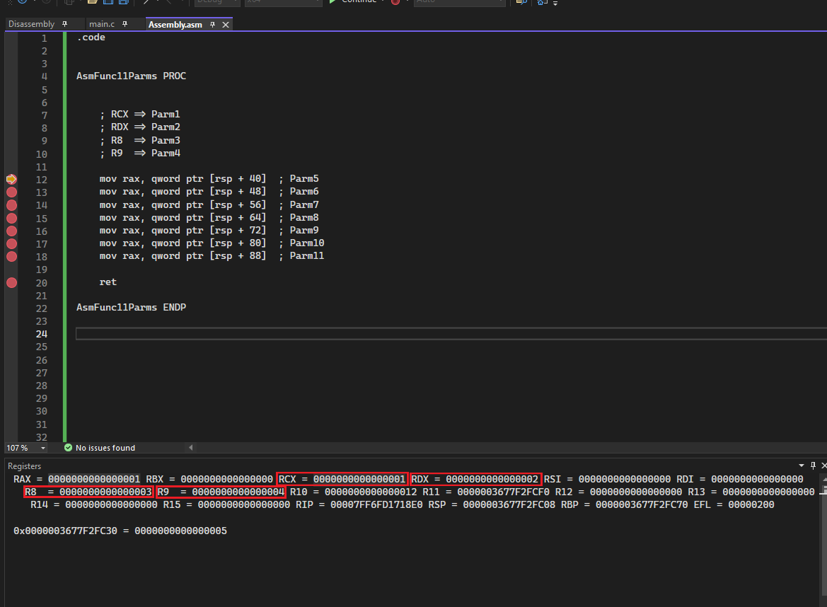
The following images show the rest of the parameters being moved to the rax register. The 5th and the 6th parameters in the rax register, respectively:
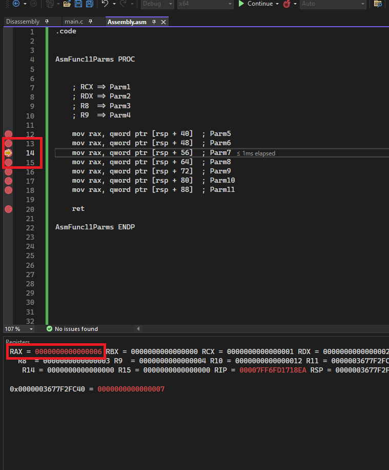
The 10th and the 11th parameters in the rax register, respectively:
Returning Value
When a 64-bit MASM procedure returns a value, it stores the output in the RAX register. Before executing the ret instruction, the procedure saves the value inside the RAX register, allowing the function to return the value.
The following AddtwoNumbers procedure, takes two parameters, to return their sum.
AddtwoNumbers PROC
    mov rax, rcx    ; Moving the 1st parmeter to RAX
    add rax, rdx    ; Add the 2nd parmeter to the value in RAX
    ret             ; return (RAX here is RCX + RDX)
AddtwoNumbers ENDP
Shadow Space
As previously mentioned, even in cases where a procedure requires four or fewer parameters, there should be 32 bytes reserved on the stack for these parameters. This reserved part of memory is called the shadow space and is deducted from the stack pointer register (RSP) at the start of the caller function. In the Microsoft calling convention, when calling a procedure, the caller is responsible for allocating the shadow space for its callee. Ideally, the caller should also allocate an additional 8 bytes reserved for the return address of the callee, even if the callee takes no parameters.
The shadow space is not only 40 bytes in size (size of register parameters and the return address); instead, it includes the size of all stack parameters passed to the callee, multiplied by 8. It is worth mentioning that reserving shadow space is a complicated matter that depends on the calling convention of the functions and can interfere with another topic known as stack alignment. These topics won't be discussed further in this module. However, for more information, one can check What is the shadow space in x64 assembly? or refer to Section 5.7.5 Parameter Setup and Cleanup (or “What’s with These Magic Instructions?”) in The Art of 64 Bit Assembly book. Despite this, the size of the shadow space can often be determined using the following rule:
Shadow Space Size = 32 + 8 + [8 * (number of stack parameters)] Reserving RSP's Value
Additionally, before subtracting the stack pointer register from the size of the shadow space, one should preserve its value to ensure stack alignment. This is usually done using two instructions push rbp and mov rbp, rsp, both are discussed below:
push rbpPushes the value of the base pointer register to the stack, thus saving it there. The base pointer register is typically used to reference variables on the stack within a subroutine. By pushing its current value onto the stack, the subroutine can save the previous value ofrbpand restore it later before returning to the caller.mov rbp, rspCopies the current value of the stack pointer register into the base pointer register.
Together, these two instructions set up a standard stack frame for a subroutine in 64-bit assembly. Typically, after these two instructions are executed, sub rsp, <shadow space> instruction will follow, which reserves memory for the shadow space discussed earlier.
Undoing Changes
Finally, before the procedure returns, one should undo the changes done to the base pointer and the stack pointer registers, rbp and rsp respectively. This is done using the following instructions:
mov rsp, rbpRestores the stack pointer to its original position before the subroutine was called.pop rbpPops the previous value of the base pointer register off the stack and restores it. This is the value that was saved at the beginning of the subroutine using thepush rbpinstruction.
It is worth mentioning that both these instructions can be replaced with a single leave instruction that accomplishes the same task.
Caveat
Using this method, while executing the producer's instructions, the rbp register should be untouched because it holds the original value of what the stack pointer should point to. If such information is lost (RSP's original value), upon returning from the procedure, the function may crash.
Reserving Shadow Space Example
The following AsmCallFunction procedure, calls printf with five different parameters, allocating shadow space for it. One can alter the size of the reserved shadow stack (change it from 48 to check the consequences of it on the program's execution (note that it may crash).
.data

String1     byte    '[i] AsmCallFunction => This is a string: "%s" | This is a dword: %d | This is a word: %d | This is a byte: 0x%0.2X', 10, 0
String2     byte    'Hello World!', 0
DwordVar    dword   213483
WordVar     word    23
ByteVar     byte    10

externdef printf:PROC            ; Declaring an external value as a procedure (printf in C)

.code

AsmCallFunction PROC

    push rbp                        ; Setting up AsmCallFunction's shadow space
    mov rbp, rsp
    sub rsp, 48                     ; 32 bytes (4 parameters) + 8 bytes (5th parameter) + 8 byte (return address of printf)

    lea rcx, String1                ; 1st parameter
    lea rdx, String2                ; 2nd parameter

    xor r8, r8                      ; 3rd parameter
    mov r8d, DwordVar

    xor r9, r9                      ; 4th parameter
    mov r9w, WordVar

    xor rax, rax                    ; 5th parameter
    mov ah, ByteVar
    mov byte ptr [rsp + 32], ah     ; '32' represents the size of the stack reserved for the register parameters of "AsmCallFunction". Thus a 5th p
arameter will start at this offset from RSP

    call printf                     ; Calling printf

    leave                           ; "mov rsp, rbp" & "pop rbp"
retAsmCallFunction ENDP
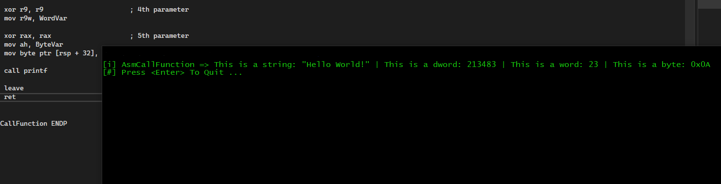
endCalling the above AsmCallFunction procedure will produce the following:
Video Demo
Conclusion
In conclusion, this module provided an overview of the fundamental concepts and techniques used in MASM assembly programming. The included code available for download provides examples of the topics discussed throughout this module. By studying and practicing the code, readers can gain a deeper understanding of how assembly language works and develop the skills necessary to create their own programs.
The assembly concepts explained in this module will suffice for the user for any upcoming modules that require assembly knowledge.
Companion Project & Source Code
5 readable source/config files extracted directly from the archive
; @NUL0x4C | @mrd0x : MalDevAcademy


.data

; All the below variables are used in "AsmCallFunction" only

String1     byte    '[i] AsmCallFunction => This is a string: "%s" | This is a dword: %d | This is a word: %d | This is a byte: 0x%0.2X', 10, 0
String2     byte    'Hello World!', 0
DwordVar    dword   213483
WordVar     word    23
ByteVar     byte    10

; The following string is used in "AsmHelloWorld"

HelloStr    byte    'Hello World !', 10, 0

externdef printf:PROC                               ; Declaring an external value as a procedure (printf in C) - used in "AsmCallFunction" & "AsmHelloWorld"


.code

;
;   A function that demonstrate the push & pop instructions and there affect on the stacl
;
SimplePushPop PROC

    push 3              ; rsp - 8
    push 2              ; rsp - 8
    push 1              ; rsp - 8

    mov eax, [rsp]      ; eax = 1
    mov ebx, [rsp + 8]  ; ebx = 1
    mov ecx, [rsp + 16] ; ecx = 1

    add rsp, 24         ; This substitutes x3 pop instructions

    ret

SimplePushPop ENDP


;
;   A function that demonstrate passing more than 4 parameters (on the stack)
;
AsmFunc11Parms PROC


    ; RCX => Parm1
    ; RDX => Parm2
    ; R8  => Parm3
    ; R9  => Parm4

    mov rax, qword ptr [rsp + 40]  ; Parm5
    mov rax, qword ptr [rsp + 48]  ; Parm6
    mov rax, qword ptr [rsp + 56]  ; Parm7
    mov rax, qword ptr [rsp + 64]  ; Parm8
    mov rax, qword ptr [rsp + 72]  ; Parm9
    mov rax, qword ptr [rsp + 80]  ; Parm10
    mov rax, qword ptr [rsp + 88]  ; Parm11

    ret

AsmFunc11Parms ENDP


;
;   A function that demonstrate returning values
;
AddtwoNumbers PROC
    mov rax, rcx    ; Moving the 1st parmeter to RAX
    add rax, rdx    ; Add the 2nd parmeter to the value in RAX
    ret             ; Return (RAX here is RCX + RDX)
AddtwoNumbers ENDP


;
;   A function that demonstrate shadow space allocation & cleanup
;
AsmCallFunction PROC

    push rbp                        ; Setting up AsmCallFunction's shadow space
    mov rbp, rsp
    sub rsp, 48                     ; 32 bytes (4 parameters) + 8 bytes (5th parameter) + 8 byte (return address of printf)

    lea rcx, String1                ; 1st parameter
    lea rdx, String2                ; 2nd parameter

    xor r8, r8                      ; 3rd parameter
    mov r8d, DwordVar

    xor r9, r9                      ; 4th parameter
    mov r9w, WordVar

    xor rax, rax                    ; 5th parameter
    mov ah, ByteVar
    mov byte ptr [rsp + 32], ah     ; '32' represent the size of the stack reserved for the register parameters of "AsmCallFunction". Thus a 5th parameter will start at this offset from RSP

    call printf                     ; Calling printf

    leave                           ; "mov rsp, rbp" & "pop rbp"
	ret


AsmCallFunction ENDP


;
;   A function that calls printf to print "Hello World!"
;
AsmHelloWorld PROC

    push rbp                     ; Setting up AsmCallFunction's shadow space
    mov rbp, rsp
    sub rsp, 40                  ; 32 bytes (4 parameters) + 8 byte (return address of printf)

    lea rcx, HelloStr            ; Calling printf
    call printf

    mov rsp, rbp                 ; Can be "leave"
    pop rbp
    ret

AsmHelloWorld ENDP


end
Full Archive Manifest (6 files inside .zip)
- IntroToAssembly/IntroToAssembly.sln
- IntroToAssembly/IntroToAssembly/Assembly.asm
- IntroToAssembly/IntroToAssembly/IntroToAssembly.vcxproj
- IntroToAssembly/IntroToAssembly/IntroToAssembly.vcxproj.filters
- IntroToAssembly/IntroToAssembly/IntroToAssembly.vcxproj.user
- IntroToAssembly/IntroToAssembly/main.c